SI2-CBB philosophy
Nederlandse tekst
After 20 years of experience with all kind of CANbus products I was triggered on a new product early 2012. Besides the CANbus also a nostalgic feeling came up. The Duinomite Mega, which was presented in the article, would bring us back to the 80's with an "old-fashioned" Basic interpreter. In the early 80's my love for computers was born with the Tandy TRS80 and many old Dutch guilders were spent to my hobby of that time. During the years the hobby has been grown to something, which does not cost guilders anymore, but brings Euro's. The mentioned piece of electronics costed just 30 Euro's and gave me a professional CANbus on one hand, and a nostalgic Basic on the other hand, so the purchase was done very quickly.
 The Duinomite Mega
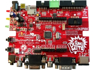
The Duinomite Mega is a single-board computer of the Bulgarian company Olimex. The hardware is fully open and can be copied by everyone. However it does not make sense in my opinion, because the price/quality quotient of the module is very good. The hardware is built around a PIC32 controller of Microchip. This controller has an Ethernet, a CANbus, an USB, an RS232, a VGA, a PS-2, and also a lot of multifunctional in- and outputs integrated. All interfaces, except the Ethernet are connected to the outside world. The multifunctional I/O through Arduino (the Duino in the name) compatible headers, which can be used for simple extensions, available from multiple suppliers. By the way: in the mean time also an eMEGA module is available for an additional 10 Euro, which also has the Ethernet connection. The most important connections for me were the CANbus and USB interfaces.
 As said before, the local software on the Duinomite Mega exists of a Basic interpreter. The DM-Basic is a version of MM-Basic, a Basic interpreter, originally developed by Geoff Graham for another PIC32 based single board system, the Maximite (the mite in Duinomite). Allthough Olimex tried to support all hardware as good as possible, the CANbus was missing in the Basic commands. This was my only disappointment, in my new so-called hobby-project at that time. DM-Basic in the mean time is a frozen version of MM-Basic. This has the disadvantage that no new functionality is added anymore, but also has the advantage, that this version is still completely "open source". MM-Basic versions are still free to download, however not in source anymore. The Duinomite Mega is still built with completely open hardware and open software and this has its advantages as we will see later on.
From hobby to serious product
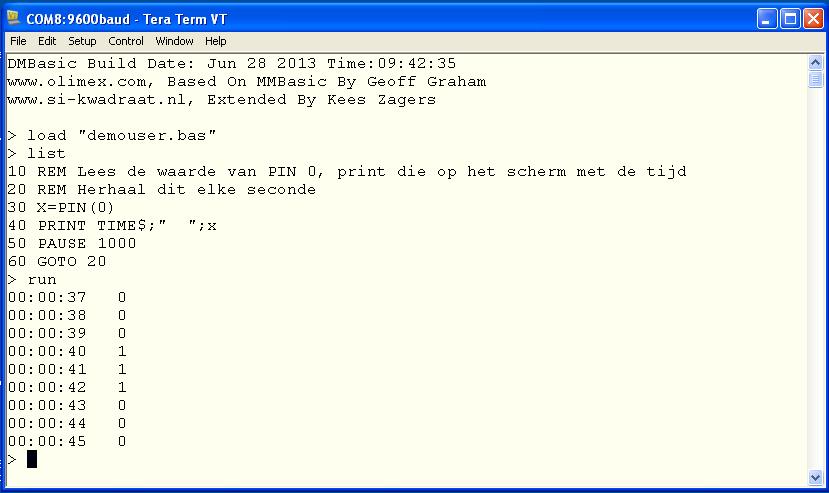
A few weeks after I had my Duinomite Mega in house, I came to the conclusion, that the hardware was much more powerful than I ever had expected. I realised that a lot of interfaces were not relevant for my applications. Interfaces like VGA and PS-2 keyboard were nice for a single board computer, but using the USB interface as terminal connection to the laptop was much more convenient. I use Teraterm with Windows XP, Vista, Windows 7 en Windows 8, without changing a driver. The Duinomite Mega is seen as a COM port, however using the speed of USB. An external powersupply is not needed anymore, the USB power has enough capacity to supply the moduleis. A low-cost uSD module of 4 GB is a perfect disk, which is not only used by the local processor, but with a simple Basic command is converted to an external hard disk for my laptop. Another pleasant surprise again.
DM-Basic made me also realise, that the programming circle was round now. After the Basic on the TRS80 in the 80's I wanted to speed up my applications and started with a Pascal compiler and even a Z80 Assembler (once one of the first products of Microsoft). DOS PC's, UNIX and real-time systems later brought me to C and even ADA. The next step was in the 90's to an advanced Windows fourth generation programming environment, Testpoint. Using this environment the CAN applications were developed. In the 90's I have also looked at Java, Labview en IEC1131 environments. When we had to make the applications also remote available, the Internet Script languages JavaScript and PHP had to be learned. Back to the embedded platform with only 128 kbyte (still 32 times more than on my original TRS80) internal RAM memory means we are back at the beginning. So "Back to Basic" is a logical step, but also now the blood is streaming faster when we are reaching the same limits as in earlier days.
The TRS80 gave me my first problems when I wanted to add extra hardware which had to be controlled from assembler routines, now I ran into trouble with my CAN interface. In the past the Assembler routines were inserted with POKE statements into the Basic program. Now I started to investigate the PIC32 CAN-controller with PEEK and POKE. So I did a download of the necessary information of the Microchip site and found out very quickly, that this CAN-controller is not an ordinary one, but a very powerfull and most of all a very flexible one. Simply by using a part of the RAM memory as FIFO, the CAN-controller can use a BASIC array to store all CAN information. After it is written in the FIFO it is possible, even by BASIC, to read the CAN messages at a lower speed. Sounds simple afterwards, but was not so logical at the start. When I had this basic functionality up and running, I took the decision to make a serious product out of this.
The CAN Blackbox was introduced. Everybody could invent their own functions for the box, however we had to offer a framework for that. The first idea was to write a Basic program, by which the box could be configured completely. After a few weeks of programming I ran into the problem of the memory limit. The maximun size of the Basic program was about 40 kbytes. That is why I split the functionality into a number of separate programs. The first version of the CBB was born.
 The SI2-CBB Standard
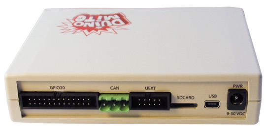
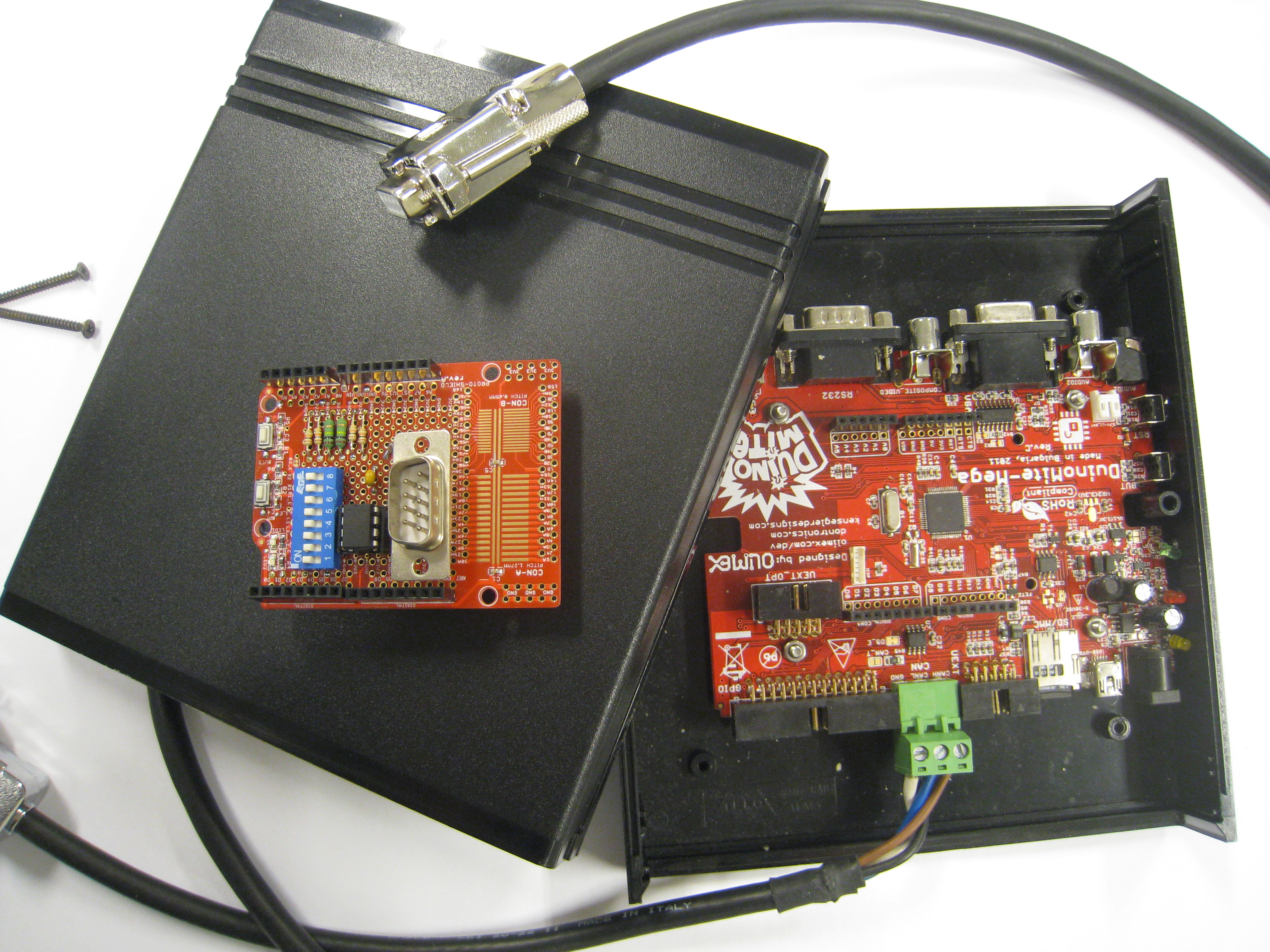
The original Duinomite Mega had a special housing from Olimex. For the hardware we added an interface cable to a 9-pin SUB-D connector for CAN, a standard USB-cable and a 4 GB uSD flash module. The hardware was complete. Dependant of the wishes of the customer we implement the usefull Basic programs. Some programs can be executed completely stand alone. E.g. a LED can be used for indication of errors on the CANbus. If the LED started blinking an error has occured. Also an automatic bitrate detection can be executed stand alone. An optimalisation program for the bitrate can be used to do some further experiments with the bitrate. The configuration of fifo's, filters, masks can also be realised by a program. The bus can be used in different states. Ofcourse we can send and receive messages on the CANbus.
I decided to deliver programs both separate and integrated on an unit. The big advantage: everything is open. One has to buy the software only once and can buy the hardware anywhere in the world. Someone who also has the hobby to program can use the code as example and write his own application. My idea was also to get a network of people working on this project and use each others programs in this way. Talking to others this seemed not the way to go. What came up, was that it would be of interest if more integrated functionality would be available in the box. The idea to use Basic only as a script language for configuring and add the other functions as firmware came up.
Our own firmware for the Duinomite Mega
As said before the Basic firmware of the Duinomite Mega is completely open source. This means, that everybody can add changes for own purposes. The changes should also be available for others. In a message of the Duinomite forum I already saw that it would be quite simple to add Basic commands. In 2012 Frank Voorburg of Feaser (http://www.feaser.com) already had made additions to the DM-Basic for the CANbus. However these were only the necessary basic commands for opening and closing of the CANbus and the receiving and sending of a message. After studying these commands I decided, that it would be possible to made a special firmware, in which much more functionality would be included. After some discussion with Frank and Olimex I started in summer months of 2012 with the new firmware. So directly again my second step in the new programming circle, the programming in C. In between I also started the third fase. As the driver of the Duinomite Mega takes care for the interfacing as a serial device, it can also be controlled by a PHP/Apache server. A mini terminal program takes care for the control from a browser: Remote control and WEB visualisation for the SI2-CBB. In one year I repeated the complete programming circle, which lasted 30 years the first time.
 The SI2-CBB Advanced and the SI2-CBB Special
In the mean time we packaged the CBB in a real blackbox. As said before, in many applications a USB- and a CANbus connection fulfill all our needs. These are now standard on the outside of the box. All other connections are optional. The box can be seen as a real replacement for one of the many CAN-USB interfaces which are on the market. Replace the computer by a USB adapter for the mains or a 12 or 24 Volt battery and we have a stand-alone CAN-logger. Connect some in- and/or outputs and we have a CAN I/O module. So the hardware possibilities are enormes. All systems having more than the two connections we call the CBB special.
The most important command, which I wanted to include in the software, is the CANLOG command. The logging of received messages is done either on the screen or on the flashdisk. Many options take care of a flexible format. Through a script a received CAN message can be translated into any protocol. CANopen and J1939 are the most standard ones, but every customer specific protocol can be implemented on the SI2-CBB too. Also the sending of CAN messages is extended in a flexible way. E.g. it is possible to use only one command to send a burst of up to 32 CAN messages. Ofcourse also commands for configuration of FIFO's, filters and masks are added. A simple Basic program can control the whole process. A number of reserved Basic variables are used for data transmission between the Basic script and the embedded CAN commands.
The use of Basic as script language
We admit that Basic does not play any role in the Internet era. Also in embedded applications the language has too many restrictions and moreover is too slow by using an interpreter in stead of a compiler. The easy commands however give a good overview of what is happening and certainly by the use of line numbers a Basic program can be read by a non-programmer. With the availability of specific CAN-commands a mechanic engineer or an electrician can develop his own applications. Plug and Play after one day.
Plug and Play applications
The SI2-CBB can also be used directly for logging of CANdata. Flexible scripts take care for specific data storage or displaying on the screen. Also the generation of CAN messages for simulation/emulation on the bus can be controlled in an easy way using a standard program. Also programs for error analysis, stress measurement and reliability measurements are available. And most of all: whatever is not of the shelve can be made fast, flexible and very cost effective.
 Dedicated hardware based on a standard module
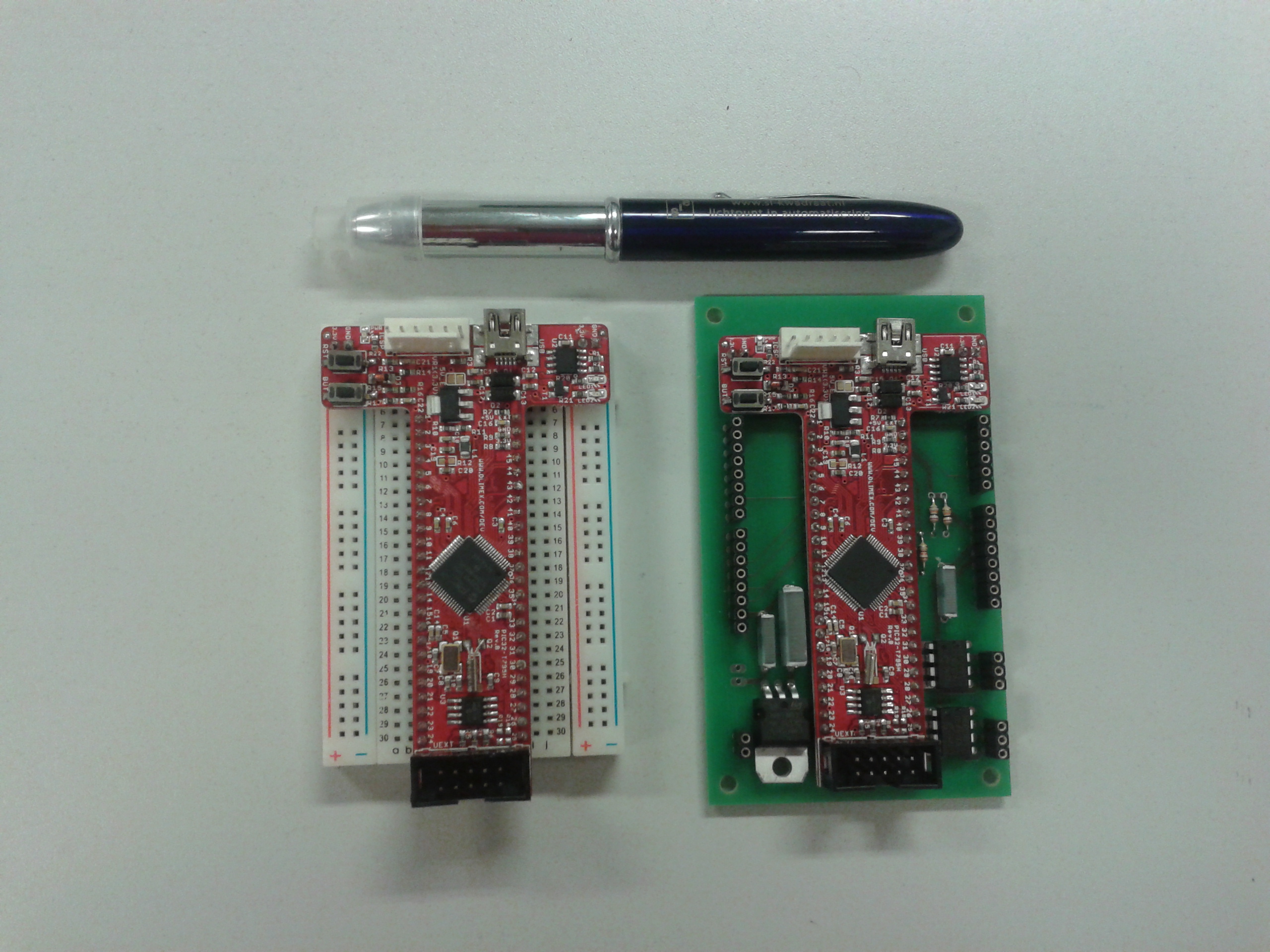
Olimex also has a modified version of the Duinomite module, which offers the possibility to manufacture an embedded system very fast. With this module we produce custom specific solutions since 2014. The base module has no CAN transceivers, but these can be added quite easily. We already did this earlier on an Arduino extension module, which has the second internal CANport of the processor connected. The module on the right has the extension with a power circuit of 12 or 24 Volt, 2 CAN transceivers and the I/O also on Arduino compatible sockets. In Basic we included a CANBRIDGE command, which offers the possibility to copy CAN messages of one port to the other and vice versa.
CANobjects live their own life with CANOBJECT
In the mean time the software has been extended by a very powerful command, which is fully optimised to the PIC32 hardware. As said before the PIC32 CAN-controller is very flexible and powerful. The power is created by a flexible RAM area, which is used for CAN messages. The area can be defined by the user. Up to 32 different objects are possible, which all can be 32 messages deep. In fact we have 32 different FIFOs each of them configured for 1 to 32 messages. Each FIFO can be configured for transmit or receive, where filters and masks can be programmed. In this way every FIFO gets its own task within the total process.
I have been thinking for a long a long time how to make optimal use of this powerful structure and the most applications were simply realised with only two FIFOs, one for receive and one for transmit. In Basic an interrupt routine is used, which is called on a time base with a resolution of 1 ms. Further study teached me, that the same 1 ms interrupt is used for the real-time clock. Why not use the same interrupt for the CAN messages. This offers me a 1 ms resolution for transmitting CAN messages and also I can check the receive FIFOs every ms for new messages. The configuration of the FIFOs is done in the Basic program, after that the objects run stand-alone. Objects can be made dependant of each other or can also activate a Basic interrupt routine. Conclusion: it has become a very powerful mechanism with a very high grade of flexibility.
 Measuring CAN on the physical level
A special project came up in 2016. Someone was curious to see if it was possible doing some reverse engineering based on measuring of physical signals on the CANbus. As CAN is mainly an embedded network, we don't know in general which node generates which message. Someone doing measurements on vehicles, got the idea to measure signals on the physical level and by comparing the analogue values decide which message is coming from which node. To do measurements on the physical level we use a Gemac CBT-2 tester. Very fast we detected a resolution of 50 mV of this instrument. Good enough to decide if a node is within specification, however not good enough to see real differences between different nodes. The built-in ADC of the PIC32 controller has a 10 bit resolution, or about 3 mV. We started a project to see if we could realize a solution based on our SI2-CBB hardware.
First of all it was important to see if we could follow the bit pattern of a CAN message in an analogue way. This is needed to trigger the ADC on the right moment. This trigger had to be a digital input and that is why we chose the signal on the Rx input of the CANcontroller. As we cannot reach this pin on the base module, we decided to use the second CAN port on an Arduino shield. Inputs on the PIC32 controller can be linked directly to an interrupt routine. Two different inputs we have used, one which starts a routine at the change from high to low and a second one for the change of low to high. The complete pattern could be followed up to a CAN speed of 500 kb/sec. As we only need to measure the dominant level in principle, we can also work with just one slope. In this way it was possible to go up to 1 Mb/sec. The ADC is triggered with this signal. The conversion time is in principe 1 uS, but with the delay in triggering and the data handling we calculate 2 or 3 uS. That is why we made a setting in which it is possible to accept only measurements when the bus stays dominant during 2 to 5 periodes. In the end it was not possible to use the development for the original purpose, but we have realized a nice new statement, CANPHYS.
CANPHYS can only be used with the additional hardware. It gives results for the analogue values of both CAN High and CAN Low, but also for the timing, measured with a very accurate clock, about 0,01 uS. All physical measurements can be done in a very flexible way.
 Low level scripts add special CAN commands
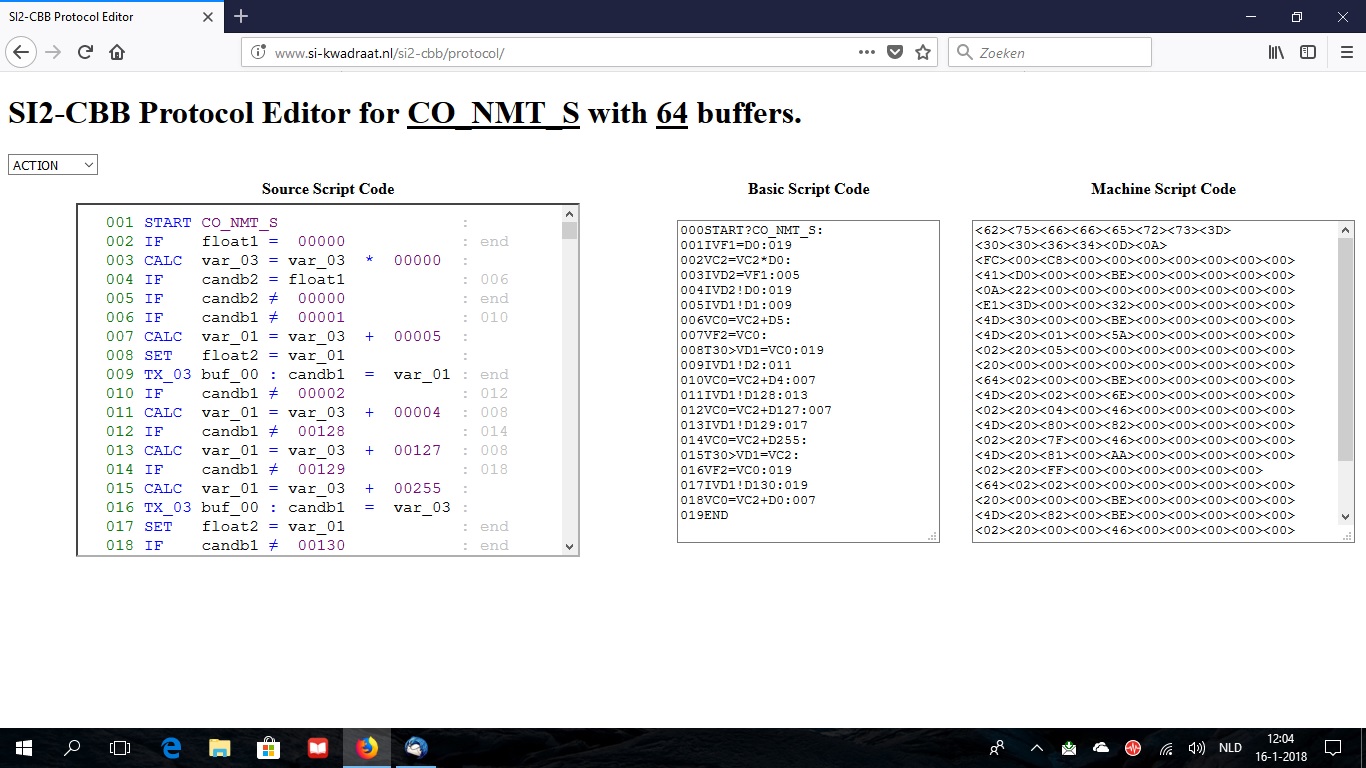
2017 was the year of the CANSCRIPT statement, which I have added. As mentioned before I made my own scripting language for analysis conform protocols like CANopen and J1939. Using four main instructions, CALC, IF, WRITE and SPEC, it is possible to convert data line by line into the right format. By adding some SPEC (read: special) commands, it became possible to transmit messages, add or edit CANOBJECTs and write and read data to a flexible BASIC array. The new CANSCRIPT commando adds the possibility to use up to 16 different scripts in the system. In fact it is possible to use own CAN commands in this way. An online editor is available for this purpose. Using CANSCRIPT we have made a CANopen slave example program, in which different CANopen objects, like PDOs, SDOs, EMCYs, SYNC, Timestamp, heartbeat and NMT state machine, are included in separate scripts. This CANopen slave module has the advantage of very flexible configurable I/O.
Everything based on the 1 mS clock
Early 2018 version 2.0 of the SI2-CBB software has been released. Besides the CANOBJECT statement in this version also the PWM statement has been added, which is also based on the 1 mS clock. Using this statement up to 8 digital outputs can be used as analogue output based on PWM. In version 2.1, introduced by the end of 2018, this statement has been further optimised. The analogue output can be controlled also using the SETPIN and PIN commands. Working on this I got the idea to measure and control also the other I/O based on the previous mentioned 1 mS clock. By linking the I/O also to the data of CANOBJECTs we don't need the Basic anymore to measure or control the I/O in a loop. For this purpose I introduced the CANIOLINK statement. An optional correction of the data can take place based on a configurable gain/offset and even using a complex calculation using another Basic statement (e.g. Sine or Logarithmic). Using an universal Basic program we can do a sequence of CANbus initialisation, CANOBJECTs configuration and CANIOLINKs configuration. A configuration file is written and the next time the configuration is loaded automatically. The Basic program is ended, leaving I/O and CANbus communication up and running.
Additions concerning the video memory
In 2019 I have decided that in fact all the necessary CAN functionality is available within the SI2-CBB. That is why I started with something, which was not important within the CAN applications, the video memory. In general the unit is connected to a computer through USB and is not used stand-alone with monitor and keyboard. In the embedded unit these interfaces are not available anyway. However besides the hardware interfaces (VGA/keyboard) also a big amount of RAM (26KB) is used by this functionality. Also the refreshing, which is done continuously uses quite some CPU performance.
In version 2.2 of the software we can disable the video memory. In this way the memory comes available as extended RAM. This can be used either as extra program memory or for a large array (_EXTMEM). To make this possible I have changed the GOSUB command. It still can be used for calling a subroutine by line number, however now also by name. The subroutine has to be written in an array in this case. This array can also have the name _EXTMEM, meaning the subroutine is in the extended memory. The routines are written in the so-called token structure, meaning all commands, functions and operators are translated into tokens. In this version a program can be saved and loaded in both the Basic text form as in the token form. The last one has 3 advantages: it is smaller, faster and unreadable for others. The last issue means that users can not change the code. Basic has become less open, however has the advantage that not everyone can edit the program is such a way that it does not work anymore.
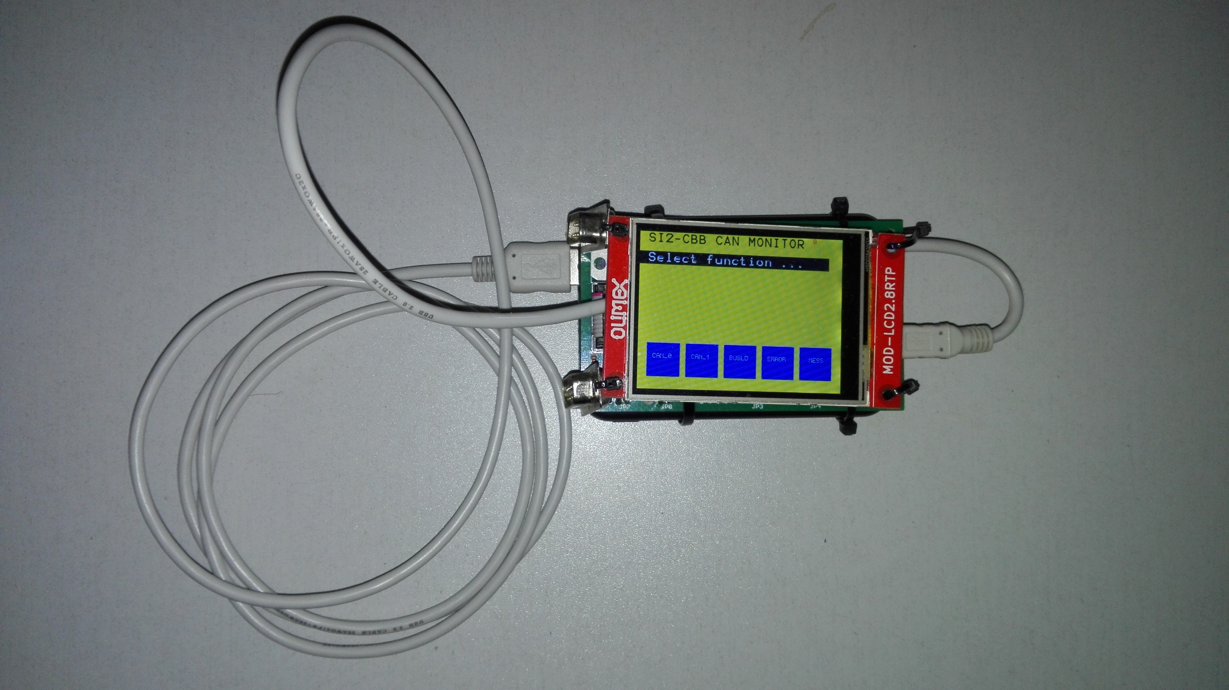
After version 2.2 a new version 2.3 has been released by the end of 2019. Besides the extensions of version 2.2 it supports two embedded displays of Olimex. Already in version 2.0 I had inclued the OLED command, which copies a small part of the video memory to a small embedded OLED display (MOD-OLED-128x64). A newer display, including a touchscreen (MOD-LCD2.8RTP) has been added in version 2.3. This can display a larger part of the video memory (320x240), or in the composite video mode even the complete video memory. Also support of the touchscreen is included. To make this possible the OLED command has been extended. If fact the command should have another name, but in that case it would not be compatible with earlier versions. Together with the embedded SI2-CBB we can now have a small stand-alone measurement system for one, or even two CAN ports. Full control and visualisation on one display.
 The year 2020, start of a new decade with new functionality
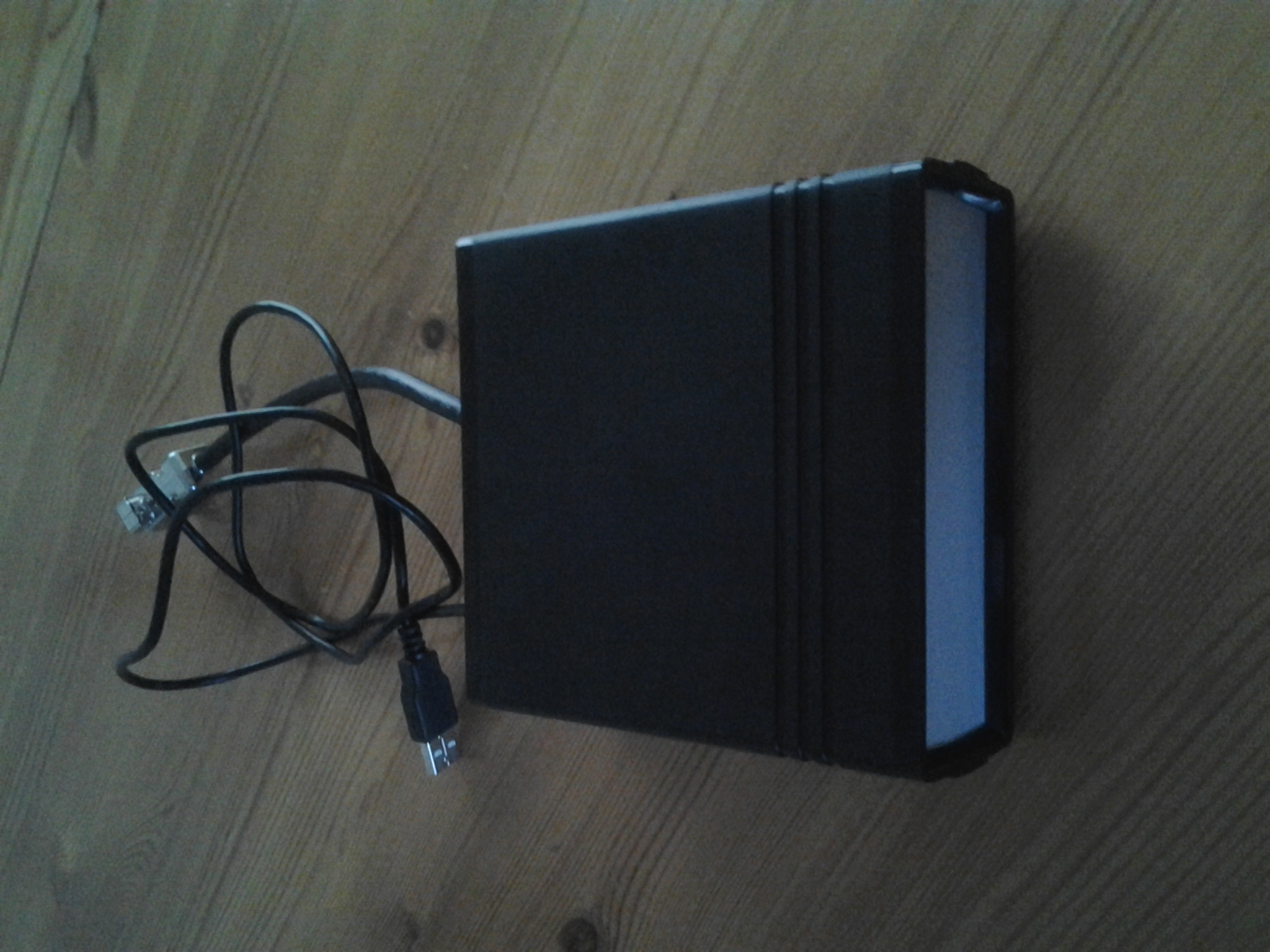
In 2020 I worked on a universal software for the small stand-alone embedded CAN analyser. By several scripts we can configure custom specific instruments. Analysis based on rough CAN data, but also CANopen, J1939, OBD-II or a complete own protocol based. Several protocols can be saved in the system and changing protocol can be done in seconds. The photo shows a prototype hardware. It would be nice if someone could build a nice fitting housing.
Although it was not my target to add extra functionality in the firmware, I detected in the testproject some missing issues in the CANOBJECT command and also that I started some things for analysis of the serial interfaces, however never implemented. As we are in the Covid-19 lockdowns, I have enough time to extend this now. I detected that we have 4 serial interfaces, however the support on these interfaces was not as it should be. So first update this. Interesting is that the port on the UEXT connector with the addition of an Olimex MOD-RS485 of MOD-RS485-ISO fully supports the RS485 networks by the 9-bit data structure. The COMLOG command has been made in such a way that it supports more than one COM ports in parallel. In this way the SI2-CBB is also a COM BLACK BOX.
An addition to the CANOBJECT command consists of the interpretation of the databytes in the Transmit object. With the variabel CANOBJxxDATA(y) the value of databytes is entered. This value is normally from 0 to 256. In the new version this can also be higher, in such a way that without user interception the value automatically changes by a certain pattern. For testing of a CAN installation very usefull.
 CAN over the power lines
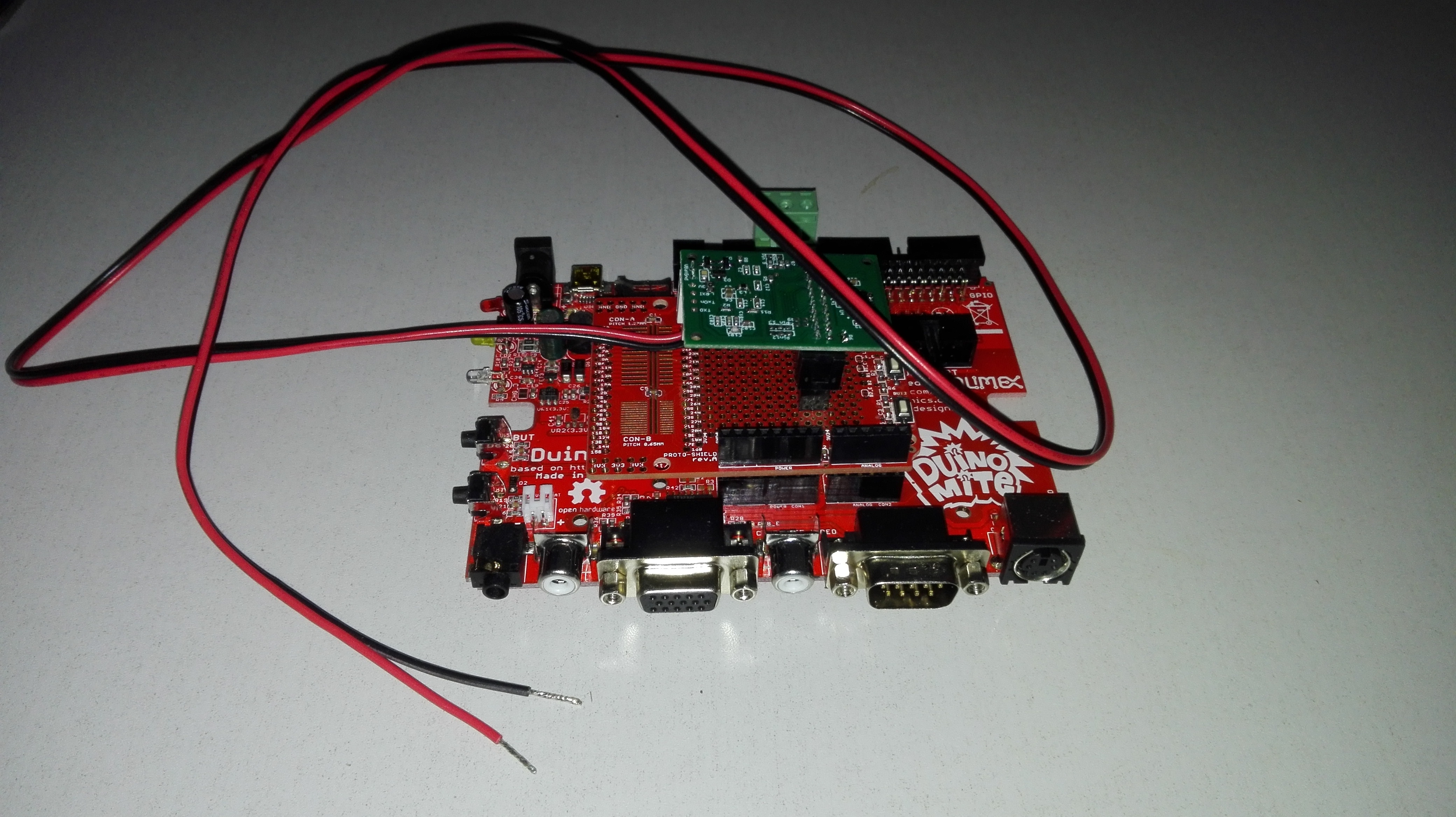
A special project appeared in 2021. A machinebuilder wanted to use CAN, however this had to be done over so-called slip rings, 2 power lines en 2 CAN lines. These slip rings were very noisy on the CAN signal. Looking for alternatives brought us to a system of the Israelian company Yamar, which modulated the CAN signal on a higher frequency on the power lines. I was asked to test this under several circumstances. We have done this with the SI2-CBB on the second CAN port without the CAN transceiver, but in stead of that the DCAN500C module of Yamar. By placing this module on the Arduino connectors we created a system with only 2 wires to the outside world for both power and CAN. See the picture.
 Remote entry to the SI2-CBB through the Internet
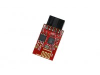
Several years ago a used a bluetooth interface (MOD-BT) to control the SI2-CBB by my smartphone through a terminal program. This can be usefull to control wireless at some location, however no additional advantages. More usefull is to control it by WIFI and the Internet. This is possible by the embedded IOT modules of Olimex (eg. MOD-WIFI-ESP8266). Many hours I spent in 2021 to get a good remote interface for the SI2-CBB. Now we can communicate with every SI2-CBB anywhere in the world, if it is extended by the SI2-ESP (an ESP8266 interface with our firmware). Both based on a simple Telnet protocol, as on an advanced website. This website is not yet available for everyone, however it can be tested for by interested people. Communication can be done by giving Basic commands, but also in real-time in a running program. Also possible is upload/download of files by the XMODEM protocol. It was a complex issue by the combination of Basic (including the C-sources for e.g. the XMODEM protocol), the Arduino IDE (C-like compiler), PHP and JavaScript. A real challenge.
New manual for version 2.4
In 2021 I have completely rewritten the manual. Both existing Basic commands combined with the extra functionality, used to get to the SI2-CBB. This manual can be downloaded at: http://www.si-kwadraat.nl/si2-cbb/manuals/en/can-manual2_4.pdf.
In 2022 I decided to make the last version 2.5 of the Basic software. Only a few additions, like opening a COM poort AS REMOTE to control the SI2-ESP. Also an option to disable the CTRL-C to prevent interupting a run-time program. The complete manual can be found at: http://www.si-kwadraat.nl/si2-cbb/manuals/en/can-manual2_5.pdf
The new project I started is the specific CAN software in an Arduino IDE library. More about this later on.